AXESS 99-5839CH Manual
AXESS
Not categorized
99-5839CH
Read below 📖 the manual in Italian for AXESS 99-5839CH (32 pages) in the Not categorized category. This guide has been helpful for 9 people and has been rated 4.5 stars on average by 2 users
Page 1/32

I N S TA L L AT I O N I N S T R U C T I O N S
99-5839CH
Metra. The World’s Best Kits.®MetraOnline.com © COPYRIGHT 2023 METRA ELECTRONICS CORPORATION REV. 2/7/23 INST99-5839CH
Patent # 10,579,232
Attention! With the key out of the ignition,
disconnect the negative battery terminal
before installing this product. Ensure that all
installation connections are secure before
cycling the ignition to test this product.
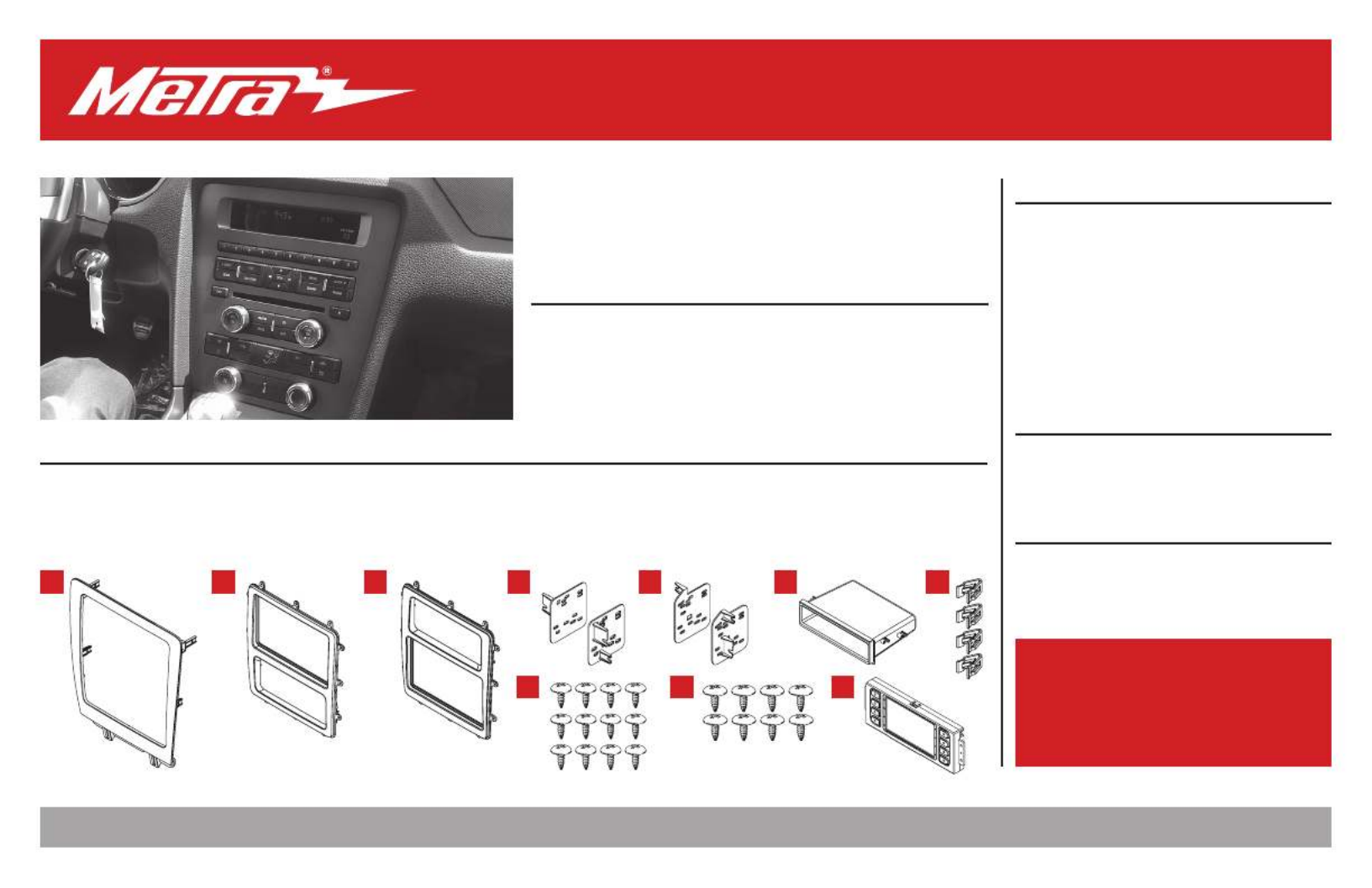
KIT FEATURES
• ISO DIN radio provision with pocket
• ISO DDIN radio provision
• Touchscreen interface for climate and personalization features
• Painted charcoal with a matte black center
KIT COMPONENTS
• A) Radio/Display trim panel • B) Radio/Display sub-trim panel upper (a) • C) Radio/Display sub-trim panel lower (b) • D) Radio brackets upper (a)
• E) Radio brackets lower (b) • F) Pocket • G) (4) Panel clips • H) (12) #6 x 3/8” Phillips pan-head screws • I) (8) #8 x 3/8” Phillips truss-head screws
• J) Touchscreen display assembly and wiring harness • K) Antenna adapter (not shown)
TOOLS REQUIRED
• Panel removal tool • Phillips screwdriver
• 9/32” socket wrench
TABLE OF CONTENTS
Dash Disassembly ..................................................2
Kit Preparation .......................................................3
Kit Assembly
–ISO DIN radio provision with pocket ..................4
–ISO DDIN radio provision .....................................5
Axxess Interface Installation ............................6-15
Final Assembly ..................................................... 10
WIRING & ANTENNA CONNECTIONS
Wiring Harness: Axxess interface built
into touchscreen
Antenna Adapter: Included with kit
Steering wheel control interface: Included with kit
A B C D
H I J
E F G
Ford Mustang 2010-2014
Visit for more detailed information about the product and up-to-date vehicle MetraOnline.com
specific applications

2386.257.1187
|
MetraOnline.com
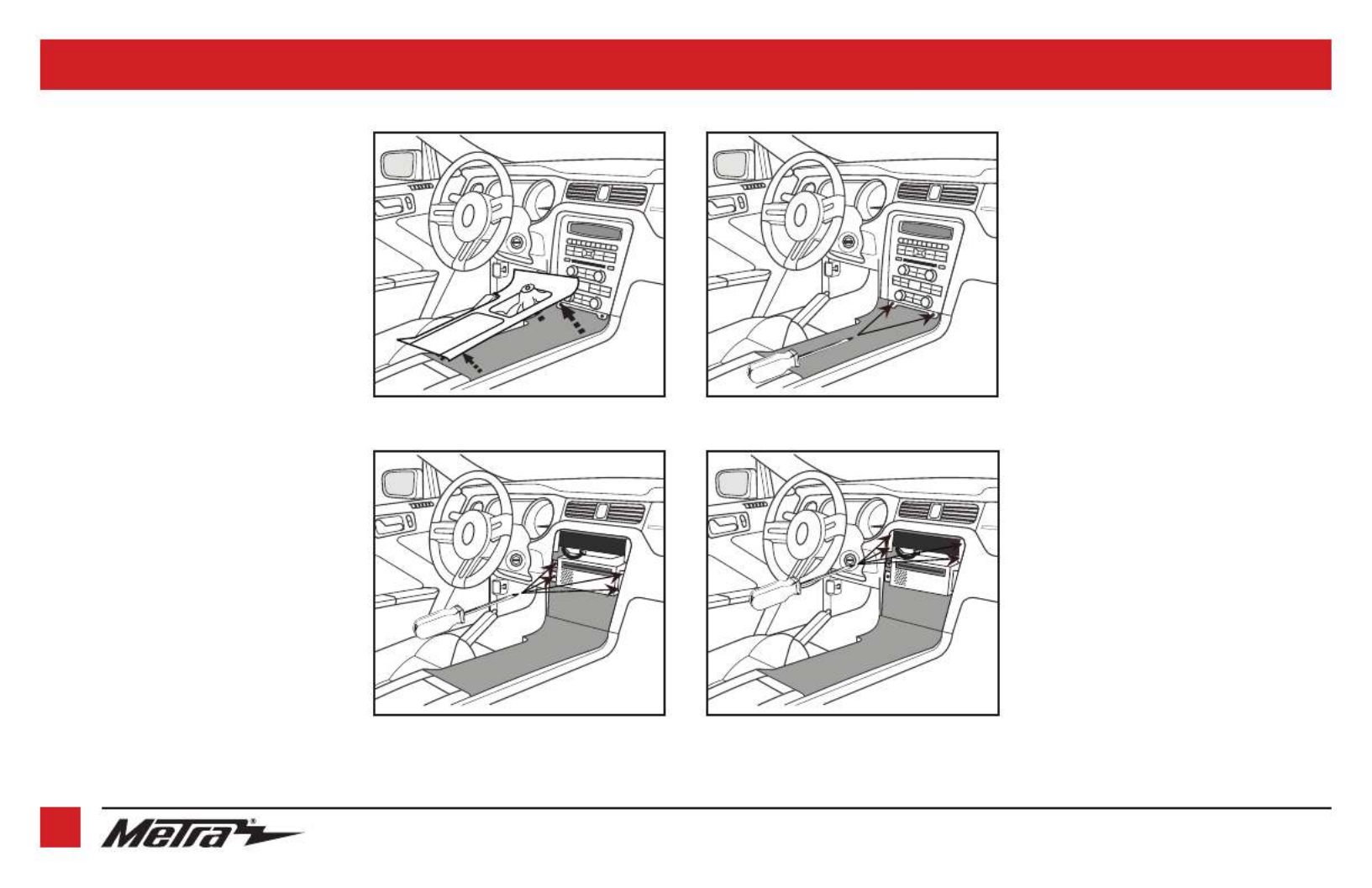
DASH DISASSEMBLY
1. Unclip and remove the trim panel
surrounding the shifter, including the
cup holders. (Figure A)
2. Remove (2) 9/32” screws from the
bottom of the radio/climate control
panel, then unclip and remove the
panel. (Figure B)
3. Remove (4) Phillips screws securing the
radio chassis to the vehicle. Slide the
chassis out, then unplug and remove.
(Figure C)
4. Remove (4) Phillips screws securing the
radio display to the vehicle. Slide the
display out, then unplug and remove.
(Figure D)
Continue to Kit Preparation
(Figure C) (Figure D)
(Figure B)(Figure A)
3
REV. 2/7/23 INST99-5839CH
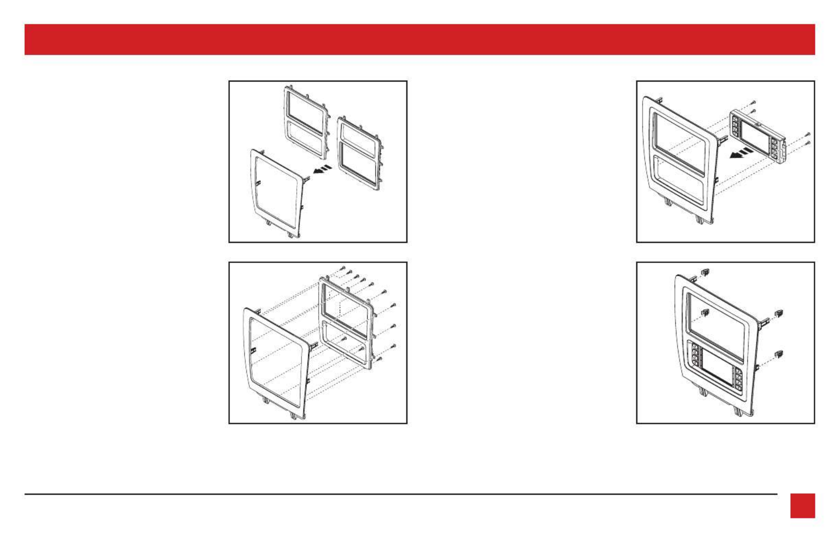
KIT PREPARATION
1. There are two different radio/display
sub-trim panels to choose from. One for
mounting the radio in the upper portion
of the kit, and another one for mounting
it in the lower portion. (Figure A)
If mounting the radio in the upper
portion, a factory module will need to
be re-located:
a. Remove the module from the sub-
dash and relocate it to the bottom
of the dash opening. The mounting
brackets attached to the module will
need to be bent outward to make
room for the radio.
(Figure B) (Figure D)
(Figure A) (Figure C)
2. Attach the desired radio/display
sub-trim panel radio/display to the
panel using the (12) #6 x 3/8” pan-head
screws provided. (Figure B)
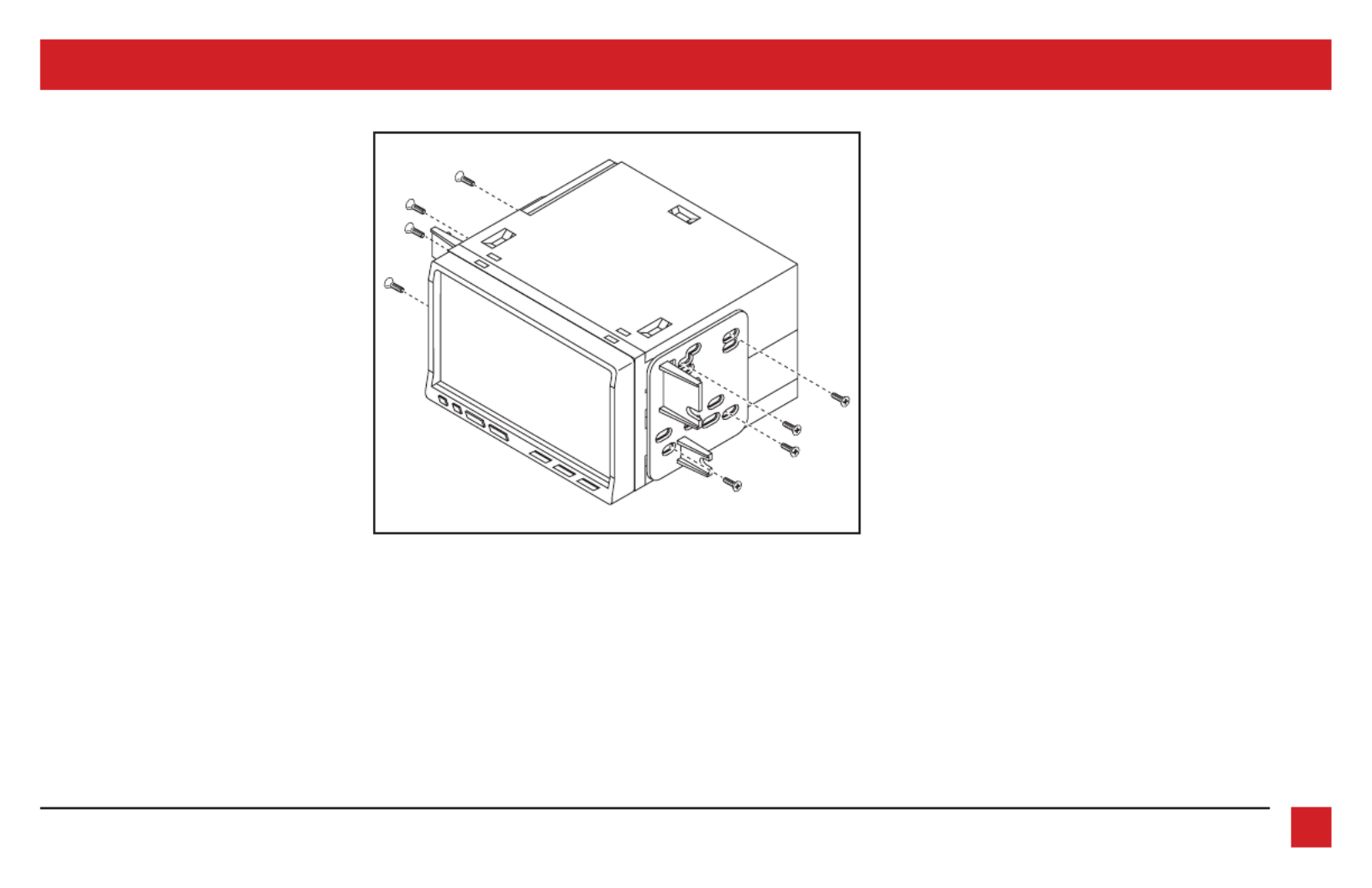
3. touchscreen display Attach the
assembly radio/display sub- to the
panel using the (4) #8 x 3/8” truss-head
screws provided. (Figure C)
4. Attach the (4) provided to panel clips
the radio/display panel. (Figure D)
Continue to Kit Assembly
4386.257.1187
|
MetraOnline.com
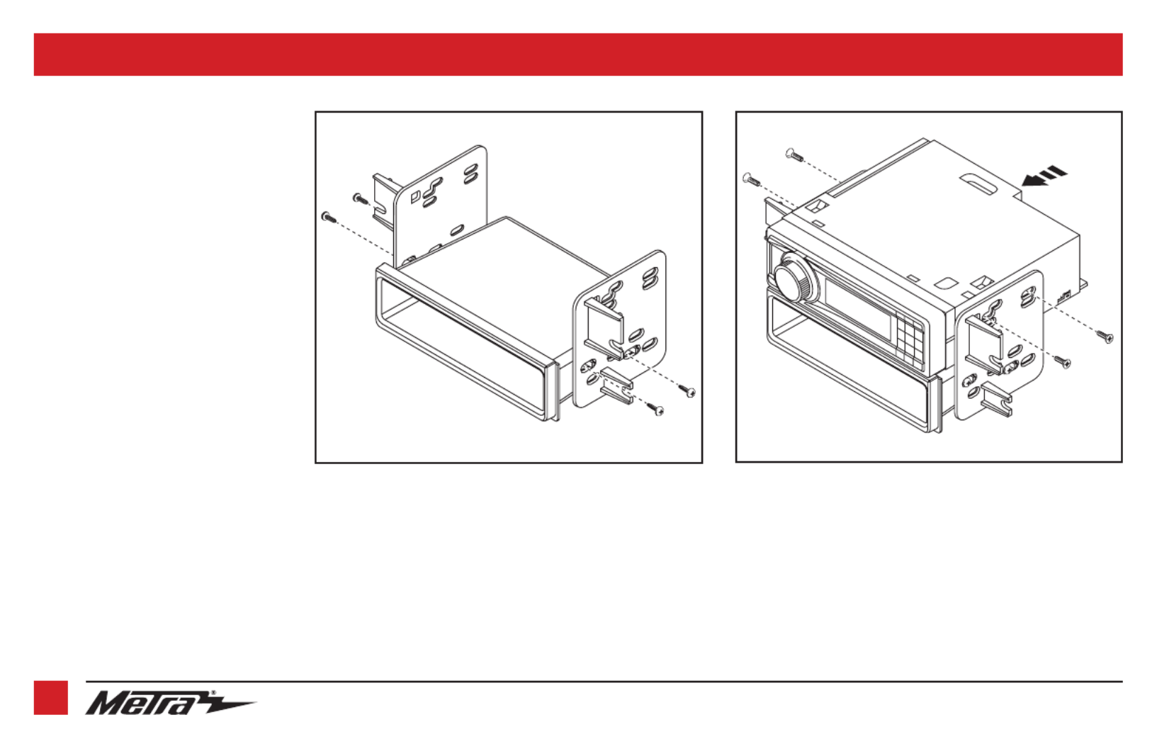
KIT ASSEMBLY
(Figure A) (Figure B)
ISO DIN radio provision with pocket
1. Attach the to the appropriate pocket
radio brackets using the (4) #8 x 3/8”
Phillips truss-head screws provided.
(Figure A)
2. Remove the metal DIN sleeve and trim
ring from the aftermarket radio.
3. Slide the radio into the bracket/pocket
assembly, and then secure it using the
screws supplied with the radio.
(Figure B)
Continue to Axxess
Interface Installation

REV. 2/7/23 INST99-5839CH 7
CONNECTIONS
From the 16-pin harness with stripped leads to the aftermarket radio:
• Connect the wire to the accessory wire.Red
• If the vehicle is equipped with a Shaker/Shaker-Pro sound system or NAV, connect the Blue/
White wire to the amp turn on wire. This wire must be connected to hear sound from the
factory amplifier.
• If the aftermarket radio has an illumination wire, connect the Orange/White wire to it.
•
If the aftermarket radio has a mute wire and the vehicle is equipped with SYNC, connect the
Brown wire to it. If the mute wire is not connected, the radio will turn off when SYNC is activated.
• Connect the wire to the right front positive speaker output.Gray
• Connect the Gray/Black wire to the right front negative speaker output.
• Connect the White wire to the left front positive speaker output.
• Connect the White/Black wire to the left front negative speaker output.
The following (3) wires are only for multimedia/navigation radios that require these wires.
• Connect the wire to the VSS/speed sense wire.Blue/Pink
• Connect the wire to the reverse wire.Green/Purple
• Connect the Light Green wire to the parking brake wire
• Tape off and disregard the following (4) wires, they will not be used in this application:
Green Green/Black Purple Purple/Black, , ,
From the 5839 harness to the aftermarket radio:
• Connect the wire to the ground wire.Black
• Connect the Yellow wire to the battery wire.
• Connect the wire to the power antenna wire.Blue
• If the vehicle is equipped with NAV, connect the Blue/White wire with a red connector to the
amp turn on wire. This wire must be connected to hear sound from the factory amplifier.
• Connect the wire to the left rear positive speaker output.Green
• Connect the wire to the left rear negative speaker output.Green/Black
• Connect the wire to the right rear positive speaker output.Purple
• Connect the wire to the right rear negative output.Purple/Black
• For models
with
SYNC: Connect the Red and RCA jacks labeled “RSE/SYNC/SAT”, to the White
audio AUX-IN jacks. Disregard the and RCA jacks labeled “FROM 3.5”, they will not Red White
be used in this application.
• For models
without
SYNC: White Connect the Red and RCA jacks labeled “FROM 3.5”, to the
audio AUX-IN jacks. Disregard the and RCA jacks labeled “RSE/SYNC/SAT”, they Red White
will not be used in this application.
• Disregard the DIN jack, it will not be used in this application.
LD-FD54PTT SYNC bypass harness:
For bluetooth control of the aftermarket radio from the factory SWC. Unplug the factory
SYNC module located behind the glove box, then tap the Yellow/Red 5839 harness on with
the Gray/Red 54PTT harnessfrom the .
Continued on the next page

386.257.1187
|
MetraOnline.com
8
3.5mm jack - steering wheel control retention:
The 3.5mm jack is to be used to retain audio controls on the steering wheel control.
• For the radios listed below: Connect the , to the male female 3.5mm connector with stripped leads
3.5mm SWC jack from the . Any remaining wires tape off and disregard.5839 harness
•
Eclipse: Connect the steering wheel control wire, normally , to the wire of Brown Brown/White
the connector. Then connect the remaining steering wheel control wire, normally Brown/White,
to the Brown wire of the connector
.
•
Metra OE:
Connect the steering wheel control Key 1 wire
(Gray)
to the
Brown
wire.
•
Kenwood or select JVC with a steering wheel control wire:
Connect the
Blue/Yellow
wire to the
Brown
wire.
Note:
If your
Kenwood
radio auto detects as a
JVC
, manually set the radio type to
Kenwood
.
See the instructions under changing radio type.
•
XITE:
Connect the steering wheel control SWC-2 wire from the radio to the
Brown
wire.
•
Parrot Asteroid Smart or Tablet:
Connect the 3.5mm jack into the AX-SWC-PARROT (sold separately),
and then connect the 4-pin connector from the AX-SWC-PARROT into the radio
.
Note:
The radio must be updated to rev. 2.1.4 or higher software.
•
Universal “2 or 3 wire” radio:
Connect the steering wheel control wire, referred to as Key-A or
SWC-1, to the
Brown
wire of the connector. Then connect the remaining steering wheel control wire,
referred to as Key-B or SWC-2, to the
Brown/White
wire of the connector. If the radio comes with a
third wire for ground, disregard this wire
.
Note:
After the interface has been programmed to the vehicle, refer to the manual provided with
the radio for assigning the SWC buttons. Contact the radio manufacturer for more information.
• Connect the 3.5mm jack into the port on the radio designated for an external For all other radios:
steering wheel control interface. Refer to the manual provided with the radio if in doubt as to where the
3.5mm jack goes to.
CONNECTIONS (CONT.)
For models
with
a Shaker system:
• Connect the White RCA jack labeled “SUBWOOFER”, to the subwoofer out jack.
• Disregard the RCA jack labeled “CENTER CHANNEL”, it will not be used in this Red
application.
• Enable Audio Output Attenuation Configuration Settings in after the kit has been
programmed.
For models
with
a Shaker Pro system:
• Connect the RCA jack labeled “CENTER CHANNEL”, to the subwoofer out jack.Red
• Disregard the RCA jack labeled “SUBWOOFER”, it will not be used in this White
application.
• Enable Audio Output Attenuation Configuration Settings in after the kit has been
programmed.
4-pin harness with yellow RCA jacks:
This harness is to be used to add an aftermarket backup camera to the touchscreen
display, if so desired.
• Connect the Yellow RCA jack labeled “Rearview camera”, to the RCA jack on the
aftermarket backup camera.
• Disregard the Yellow RCA jack labeled “AUX video”, it will not be used in this
application.
REV. 2/7/23 INST99-5839CH 9
It is highly advisable to read the following steps beforehand, to ensure a clear understanding of
what is to be expected. The following steps must be done in the order that they are numbered.
With the vehicle completely off:
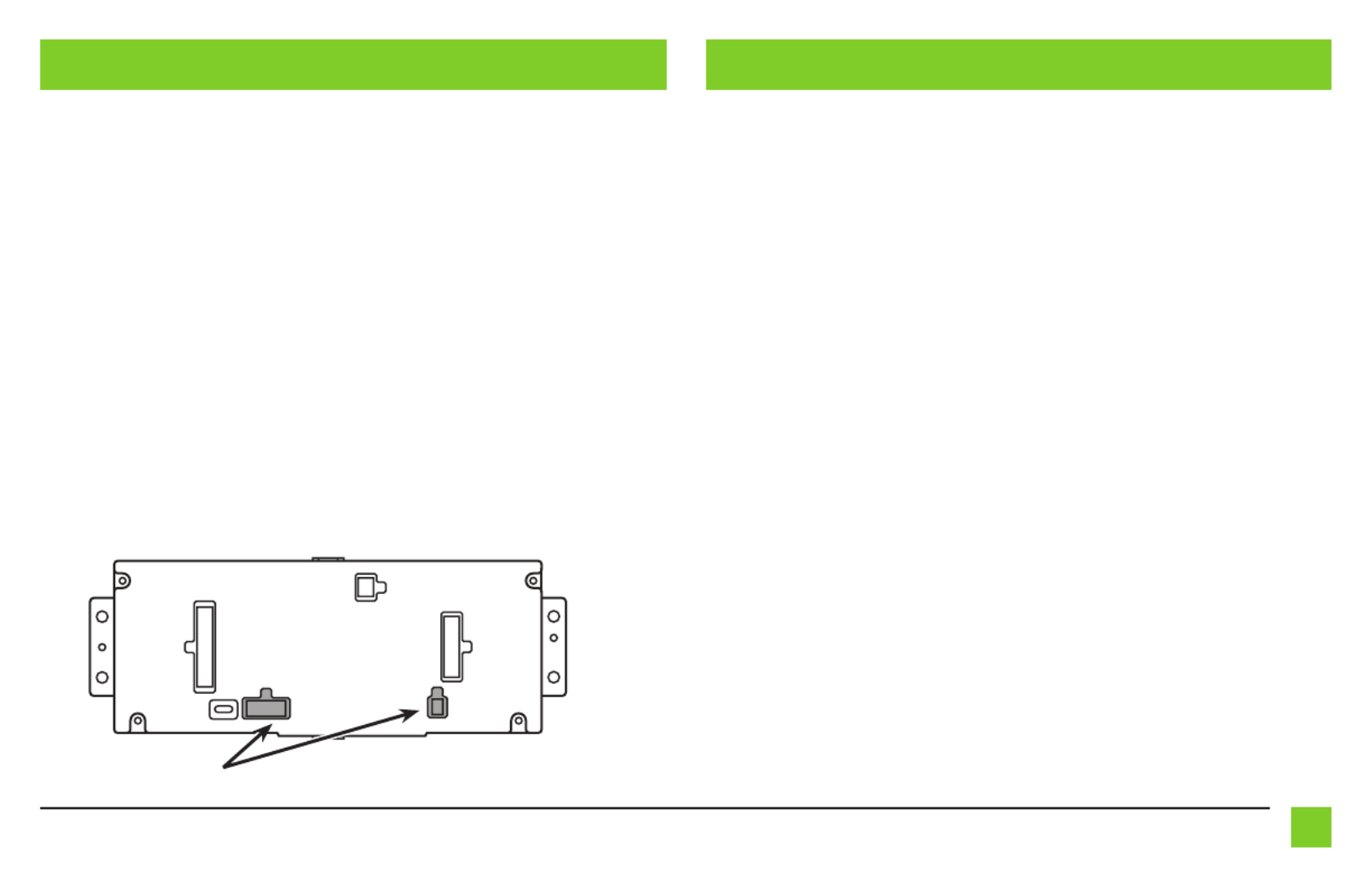
1. Connect the
16-pin harness with stripped leads
into port “B” in the touchscreen display.
2. Connect the
5839 harness
to the wiring harnesses in the vehicle. These harnesses are the
ones removed in step 3 of dash disassembly. Then insert the
5839 harness
into port “A”
in the touchscreen display. But do not install this harness until exactly before step 1 from
the
Programming
section. This is a timed process.
3.
If installing a backup camera, and the image is desired to to be displayed onto the touchscreen
display, connect the 4-pin harness with yellow RCA jacks into port “C” in the touchscreen display
.
4. Disregard ports “D” and “E”, they will not be used in this application.
5. Port “F” is an update port for future firmware upgrades.
6.
Locate the factory antenna connector in the dash and complete all necessary connections to
the radio. Use the antenna adapter provided to adapt the factory antenna connector to the
aftermarket radio.
AB
C
E
FD
INSTALLATION PROGRAMMING
1. Refer to step 2 from the Installation section.
2. Start the vehicle.
3. Program the kit:
a. Once the touchscreen display loads up, select the vehicle type.
b. Wait until the radio comes on, and the touchscreen display shows SWC Configured*.
This process may take up to 3 minutes.
f the touchscreen display does not load up, or the radio doesn’t come on within Note:
3 minutes, and/or the touchscreen display does not show SWC Configured*, check all
connections, then reset the interface and try again. Refer to the Troubleshooting section.
* For models with steering wheel controls.
4.
Cycle the key off. If the driver’s door is closed, open and close the door. Cycle the key back on.
5. Test all functions of the installation for proper operation, before reassembling the dash.
Note: DO NOT CONNECT!

10 386.257.1187
|
MetraOnline.com
1. Secure the completed assembly to the dash using the factory screws.
2. Reassemble the dash in reverse order of disassembly using the 99-5839CH radio display trim
panel.
FINAL ASSEMBLY EXTRA FEATURES
SYNC (4.2-inch display screen models only):
If the vehicle is equipped with SYNC, the 99-5839CH can retain this feature.
1. Change the source of the radio to AUX-IN.
2. Press the Info button on the touchscreen display to enter the SYNC menu. Press the climate
control icon to get back to the main menu.
REV. 2/7/23 INST99-5839CH 11
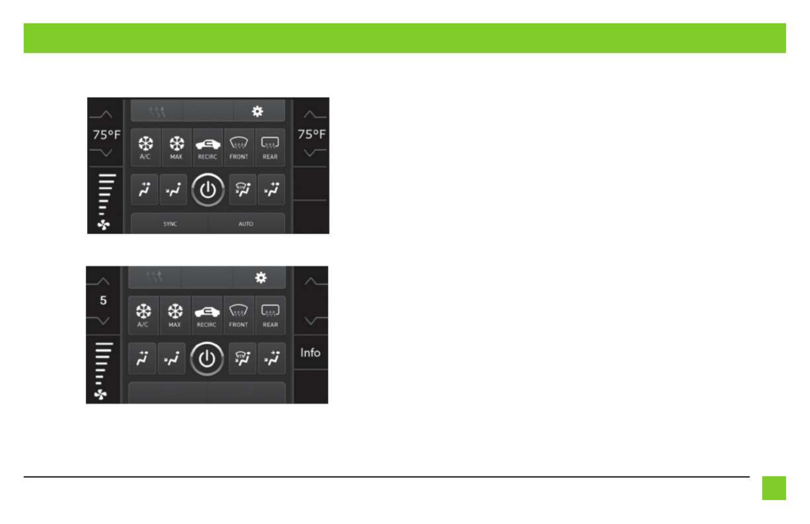
TOUCHSCREEN DISPLAY OPERATION
• This is the climate control screen which will be displayed on the touchscreen display.
This is considered the main screen.
• The upper left tab with (3) arrows will take you to the Heated/Cooled* seats screen, and the
Heated Steering* screen, if applicable.
• The upper right tab with the gear icon will take you to the Configuration Settings screen.
• Auto climate models: The climate controls will function in the same manner that they did
with the factory climate controls.
• The climate controls will function in the same manner that they Manual climate models:
did with the factory climate controls, yet via touchscreen buttons instead. The temperature
control will display a numerical scale, with “LO” being the coldest, and “HI” being the
hottest: LO / 1-9 / HI
Note: The “Info” button will only be shown if SYNC® is to be retained.
Continued on the next page
Climate Control screen
Manual climate controls
Automatic climate controls

386.257.1187
|
MetraOnline.com
12
TOUCHSCREEN DISPLAY OPERATION (CONT.)
• Backlight
• For controlling the color of the buttons and back-light intensity.
• Backup Camera
•
Enable/disables the backup camera image to the touchscreen display. Disabled by default
.
• Audio Output Attenuation*
• Enables lowering the output of the interface for models equipped with a
Shaker/Shaker Pro sound system. Disabled by default.
• Digital Amp Gain*
• For adjusting the output gain.
* Not available
• Steering Wheel Controls
• Remap Buttons – For remapping the steering wheel control buttons
• Dual Assign – For dual assigning the steering wheel control buttons (long button press)
• Select Radio – For auto detecting the radio, or changing the radio type
• System Configuration
• About - Information regarding the software in the kit
• Reset Vehicle Type - To reset the kit to default settings
• Comfort Options Override - Enable/disables factory seat temperature options.
Disabled by default.
Configuration Settings

REV. 2/7/23 INST99-5839CH 13
STEERING WHEEL CONTROL SETTINGS
Remap Buttons Dual Assign
• The interface has the ability to change the button assignment for the steering wheel
control audio buttons, except Volume-Up and Volume-Down. Follow the prompts on the
touchscreen display to remap the steering wheel control audio button(s) to your liking.
The aftermarket radio may not have all of these commands. Please refer to the Note:
manual provided with the radio, or contact the radio manufacturer, for specific commands
recognized by that particular radio.
• The interface has the capability to assign two functions to a single button, except Volume-
Up and Volume-Down. Follow the prompts on the touchscreen display to program the
button(s) to your liking.
Seek-Up and Seek-Down come programmed as Preset-Up and Preset-Down for a long Note:
button press.
Continued on the next page

386.257.1187
|
MetraOnline.com
14
STEERING WHEEL CONTROL SETTINGS (CONT.)
Select Radio
* Note: If the interface shows an Alpine radio, and you do not have an Alpine radio, that means
the interface does not detect a radio connected it, i.e., an open connection. Verify that the 3.5mm
jack is connected to the correct steering wheel jack/wire in the radio.
** Note: The AX-SWC-PARROT is required (sold separately). Also, the Parrot radio must be
updated to rev. 2.1.4 or higher through www.parrot.com.
† Note: If you have a Clarion radio and the steering wheel controls do not work, change the radio
type to the other Clarion radio type; same for Eclipse.
‡ Note: If you have a Kenwood radio and the touchscreen display shows a JVC radio, change the
radio type to Kenwood.
Eclipse (Type 1) †
Kenwood ‡
Clarion (Type 1) †
Sony / Dual
JVC
Pioneer/Jensen
Alpine *
Visteon
Valor
Clarion (Type 2) †
Metra OE
Eclipse (Type 2) †
LG
• To show which brand radio is “auto detected” to the interface, press the “Autodetect”
button. The radio detected will have a filled in circle. If the incorrect radio is shown,
select the proper radio.
• Following is a list of radio manufacturers that the interface presently acknowledges.
Others may be added at a later date. Universal “2 or 3 wire” radios can show up as any of
these radio manufacturers.
Parrot **
XITE
Philips
JBL

REV. 2/7/23 INST99-5839CH 15
Resetting the interface
Option # 1
1. With everything connected and the car running.
2. Hold the bottom (2) buttons for 3 seconds, then release. (Figure A)
(The screen will turn black and then put you in the vehicle selection screen)
3. Select your vehicle and wait till the “SWC Configured “ appears on the screen.
4. Turn ignition off and start vehicle, then test your interface.
Option #2
1.
With the vehicle running, press the Reset Vehicle Type System Configuration button mentioned in
.
2. Refer to , step 3, from this point.Programming
TROUBLESHOOTING
(Figure A)

I N S TA L L AT I O N I N S T R U C T I O N S
99-5839CH
Metra. The World’s Best Kits.®MetraOnline.com © COPYRIGHT 2023 METRA ELECTRONICS CORPORATION REV. 2/7/23 INST99-5839CH
K PNOWLEDGE IS OWER
Enhance your installation and fabrication skills by
enrolling in the most cognized and spected re re
mobile electronics school in our industry.
Log onto www.installerinstitute.com or call
800-354-6782 for mo information and take steps re
toward a better tomorrow.
Metra recommends MECP
certified technicians
Having difficulties? We’re here to help.
Contact our Tech Support line at:
386-257-1187
Or via email at:
techsupport@metra-autosound.com
Tech Support Hours (Eastern Standard Time)
Monday - Friday: 9:00 AM - 7:00 PM
Saturday: 10:00 AM - 7:00 PM
Sunday: 10:00 AM - 4:00 PM
¡PRECAUCIÓN! Todos los accesorios, interruptores,
paneles de controles de clima y especialmente las
luces del indicador de las bolsas de aire deben estar
conectados antes ciclar la ignición. Además, no
quite el radio de fábrica con la llave en la posición o
de encendido ni con el vehículo funcionando.
The World’s best kits.®MetraOnline.com © COPYRIGHT 2023 METRA ELECTRONICS CORPORATION REV. 2/7/23 INST99-5839CH
I N S T R U C C I O N E S D E I N S TA L A C I Ó N
99-5839CH
COMPONENTES DEL KIT
• A) Panel de la moldura del radio/pantalla • B) Panel de la sub moldura del radio/pantalla superior (a) • C) Panel de la sub moldura del radio/pantalla inferior (b)
• D) Soportes del radio superiores (a) • E) Soportes del radio inferiores (b) • F) Cavidad • G) (4) Ganchos para panel
• H) (12) Tornillos Phillips #6 de 3/8” Phillips de cabeza troncocónica • I) (8) Tornillos Phillips #8 de 3/8” de cabeza segmentada
• J) Ensamble de pantalla táctil con arnés de cableado
• K) Adaptador de antena (no se muestra)
HERRAMIENTAS REQUERIDAS
• Herramienta para quitar paneles
• Destornillador Phillips • Llave del tubo 9/32”
INDICE
Desmontaje del tablero ........................................2
Preparación del kit .................................................3
Ensamble del kit
– Provisión de radio ISO DIN con cavidad ............4
– Provisión de radio ISO DDIN ...............................5
Instalación de la interfase Axxess ...................6-15
CABLEADO Y CONEXIONES DE ANTENA
Arnés de cables: Incluye interfaz y arnés Axxess
Adaptador de antena: Incluido con kit
CARACTERÍSTICAS DEL KIT
• Provisión de radio ISO DIN con cavidad
• Provisión de radio ISO DDIN
• Pintura gris oscuro con centro negro mate
• Pantalla táctil para el clima y características de personalización
Ford Mustang 2010-2014
A B C D
H I J
E F G
Visite MetraOnline.com para obtener información más detallada sobre el
producto y el vehículo actualizado aplicaciones específicas.
386.257.1187
|
MetraOnline.com
DESMONTAJE DEL TABLERO
2
1. Desenganche y retire el panel de
moldura que rodea la palanca de
velocidades, incluyendo los portavasos.
(Figura A)
2. Quite los (2) tornillos de 9/32” de la
parte inferior del panel del radio/control
del clima, y luego desenganche y quite
el panel. (Figura B)
3. Quite los (4) tornillos Phillips que sujetan
el chasis del radio y quite. (Figura C)
4. Quite los (4) tornillos Phillips que
sujetan la pantalla del radio al vehículo.
Deslice la pantalla hacia afuera, luego
desenchúfela y retírela. (Figura D)
Continuar la preparación del kit
(Figura C)
(Figura B)(Figura A)
(Figura D)

386.257.1187
|
MetraOnline.com
4
ENSAMBLE DEL KIT
(Figura A) (Figura B)
Provisión de radio ISO DIN con cavidad
1. Sujete la
cavidad
a los
soportes
del radio
apropiados usando los (4)
tornillos Phillips #8 de 3/8” de cabeza
segmentada suministrados. (Figura A)
2. Quite la manga de metal DIN y el anillo
de moldura del radio de mercado
secundario.
3. Deslice el radio hacia adentro del
ensamble del soporte/cavidad y
después sujételo usando los tornillos
suministrados con el radio. (Figura B)
Continúe con la instalación
de la interfaz Axxess
REV. 2/7/23 INST99-5839CH 5
ENSAMBLE DEL KIT
Provisión de radio ISO DDIN
1. Sujete los
soportes al radio
apropiados
al radio usando los tornillos
suministrados con el radio. (Figura A)
Continúe con la instalación
de la interfaz Axxess
(Figura A)
Product Specifications
| Brand: | AXESS |
| Category: | Not categorized |
| Model: | 99-5839CH |
Do you need help?
If you need help with AXESS 99-5839CH, ask a question below and other users will answer you
Not categorized AXESS User Manuals

25 October 2024
13 October 2024
13 October 2024
13 October 2024
13 October 2024
13 October 2024
13 October 2024
13 October 2024
13 October 2024
13 October 2024
Not categorized User Manuals
- Not categorized Candy
- Not categorized Sony
- Not categorized Electrolux
- Not categorized Samsung
- Not categorized Xiaomi
- Not categorized Casio
- Not categorized LG
- Not categorized Bosch
- Not categorized AEG
- Not categorized IKEA
- Not categorized Huawei
- Not categorized Braun
- Not categorized Brondi
- Not categorized HP
- Not categorized Philips
- Not categorized Panasonic
- Not categorized Bauknecht
- Not categorized BEKO
- Not categorized Delonghi
- Not categorized Daewoo
- Not categorized DeWalt
- Not categorized Epson
- Not categorized Etna
- Not categorized Teka
- Not categorized Apc
- Not categorized Balay
- Not categorized Siemens
- Not categorized Hama
- Not categorized Petsafe
- Not categorized Vorago
- Not categorized Neewer
- Not categorized Danby
- Not categorized Bartscher
- Not categorized Hartke
- Not categorized Bertazzoni
- Not categorized Gigabyte
- Not categorized Smeg
- Not categorized Hisense
- Not categorized Gree
- Not categorized Hoover
- Not categorized EBERLE
- Not categorized Hazet
- Not categorized Fluke
- Not categorized Goobay
- Not categorized Topeak
- Not categorized Antari
- Not categorized Thermex
- Not categorized TCL
- Not categorized Russell Hobbs
- Not categorized Panduit
- Not categorized IFM
- Not categorized Avantree
- Not categorized Royal Catering
- Not categorized Hotpoint
- Not categorized Whirlpool
- Not categorized Schwaiger
- Not categorized Nabo
- Not categorized Arendo
- Not categorized Megger
- Not categorized Balam Rush
- Not categorized Noxon
- Not categorized Sanus
- Not categorized Adidas
- Not categorized Domo
- Not categorized Cayin
- Not categorized Reflexion
- Not categorized TP Link
- Not categorized Inventum
- Not categorized Totolink
- Not categorized Shokz
- Not categorized Gamma
- Not categorized Artusi
- Not categorized Medel
- Not categorized Meris
- Not categorized D-Link
- Not categorized Navitel
- Not categorized Meridian
- Not categorized AeroCool
- Not categorized Kugoo
- Not categorized Rikon
- Not categorized Neff
- Not categorized Garmin
- Not categorized Razer
- Not categorized Teufel
- Not categorized Enermax
- Not categorized Noveen
- Not categorized StarTech.com
- Not categorized Origin Storage
- Not categorized Outwell
- Not categorized Best
- Not categorized Stihl
- Not categorized Kostal
- Not categorized ZOTAC
- Not categorized Comfee
- Not categorized Imarflex
- Not categorized Edgestar
- Not categorized Audient
- Not categorized Kogan
- Not categorized Solis
- Not categorized DJI
- Not categorized Snom
- Not categorized McIntosh
- Not categorized One For All
- Not categorized Caple
- Not categorized SereneLife
- Not categorized Roesle
- Not categorized APSystems
- Not categorized GoGEN
- Not categorized Festo
- Not categorized Create
- Not categorized Furrion
- Not categorized Oreg
- Not categorized Glorious
- Not categorized Pro-Ject
- Not categorized Yamaha
- Not categorized CaviLock
- Not categorized OOONO
- Not categorized Venom
- Not categorized Kichler
- Not categorized SMART Technologies
- Not categorized Neo
- Not categorized Newstar
- Not categorized Legrand
- Not categorized Integral LED
- Not categorized Goodram
- Not categorized Goldtouch
- Not categorized Lutec
- Not categorized Vello
- Not categorized Asus
- Not categorized Cudy
- Not categorized Hayter
- Not categorized BlueBuilt
- Not categorized Eufy
- Not categorized Gys
- Not categorized Conair
- Not categorized Turmix
- Not categorized Franke
- Not categorized Husqvarna
- Not categorized Sauber
- Not categorized Shimano
- Not categorized Axis
- Not categorized Tamron
- Not categorized Liebherr
- Not categorized Carson
- Not categorized Gourmetmaxx
- Not categorized Truelife
- Not categorized Busch-Jaeger
- Not categorized ETA
- Not categorized Voltcraft
- Not categorized Axor
- Not categorized Karran
- Not categorized Elkay
- Not categorized Varaluz
- Not categorized Extron
- Not categorized Lindy
- Not categorized Aputure
- Not categorized Netgear
- Not categorized Honor
- Not categorized XP-PEN
- Not categorized Danfoss
- Not categorized Riccar
- Not categorized Orbegozo
- Not categorized Media-tech
- Not categorized Kuppersbusch
- Not categorized Mebby
- Not categorized Pioneer
- Not categorized TONI&GUY
- Not categorized Summit
- Not categorized Accucold
- Not categorized EarFun
- Not categorized Toolcraft
- Not categorized Gram
- Not categorized Lorex
- Not categorized Catit
- Not categorized NuPrime
- Not categorized Ecler
- Not categorized Roccat
- Not categorized AudioControl
- Not categorized Elsner
- Not categorized Kask
- Not categorized Digitus
- Not categorized Cabasse
- Not categorized Koenic
- Not categorized Haier
- Not categorized Beaphar
- Not categorized Sure Petcare
- Not categorized Livall
- Not categorized Monogram
- Not categorized Sortimo
- Not categorized Unicol
- Not categorized Audio-Technica
- Not categorized Lian Li
- Not categorized JLab
- Not categorized Toa
- Not categorized Marantz
- Not categorized Knog
- Not categorized Rega
- Not categorized Vox
- Not categorized Mars Gaming
- Not categorized Kerbl
- Not categorized Metra
- Not categorized Pyle
- Not categorized Sencor
- Not categorized Hobby
- Not categorized Lenovo
- Not categorized Noctua
- Not categorized Klein Tools
- Not categorized LevelOne
- Not categorized Shure
- Not categorized Michael Todd Beauty
- Not categorized GRAUGEAR
- Not categorized Trixie
- Not categorized Schneider
- Not categorized Lorelli
- Not categorized Roland
- Not categorized OBSBOT
- Not categorized SuperTooth
- Not categorized Kluge
- Not categorized Bobrick
- Not categorized Signature Hardware
- Not categorized Martin
- Not categorized Kanto
- Not categorized Scott
- Not categorized Delta
- Not categorized Kindermann
- Not categorized Robern
- Not categorized Hortus
- Not categorized DeLock
- Not categorized Coyote
- Not categorized Kidde
- Not categorized Anker
- Not categorized Growatt
- Not categorized Nanoleaf
- Not categorized Grundig
- Not categorized Mistral
- Not categorized VMV
- Not categorized S.M.S.L
- Not categorized Privileg
- Not categorized MPM
- Not categorized PeakTech
- Not categorized Niceboy
- Not categorized Engenius
- Not categorized Khind
- Not categorized Amana
- Not categorized EMOS
- Not categorized CyberPower
- Not categorized KitchenAid
- Not categorized RGBlink
- Not categorized Clean Air Optima
- Not categorized Manfrotto
- Not categorized Exquisit
- Not categorized Cosatto
- Not categorized Fluval
- Not categorized Kicker
- Not categorized Gude
- Not categorized Auna
- Not categorized Taurus
- Not categorized Heatit
- Not categorized Midland
- Not categorized Field Optics
- Not categorized Zebra
- Not categorized Yealink
- Not categorized FIMI
- Not categorized Optex
- Not categorized Frigidaire
- Not categorized Levoit
- Not categorized Maytag
- Not categorized Deye
- Not categorized Nibe
- Not categorized Ryobi
- Not categorized Dremel
- Not categorized Breville
- Not categorized Kodak
- Not categorized Velleman
- Not categorized Sharkoon
- Not categorized RIDGID
- Not categorized Laserliner
- Not categorized Segway
- Not categorized Power Dynamics
- Not categorized DataVideo
- Not categorized RGV
- Not categorized Hendi
- Not categorized Gamdias
- Not categorized Concept
- Not categorized BeamZ
- Not categorized Livoo
- Not categorized Nexa
- Not categorized Guzzanti
- Not categorized XO
- Not categorized Steinel
- Not categorized Bluesound
- Not categorized Flex
- Not categorized Chauvin Arnoux
- Not categorized Blackstar
- Not categorized Caso
- Not categorized Kenwood
- Not categorized Cambridge
- Not categorized Nobo
- Not categorized Dell
- Not categorized Ciarra
- Not categorized Brandson
- Not categorized Mybeo
- Not categorized Aplic
- Not categorized CSL
- Not categorized Zoom
- Not categorized Tru Components
- Not categorized Bearware
- Not categorized Moen
- Not categorized Viewsonic
- Not categorized B-tech
- Not categorized IMM Photonics
- Not categorized Maginon
- Not categorized Speco Technologies
- Not categorized Nec
- Not categorized IFi Audio
- Not categorized Tripp Lite
- Not categorized Nevir
- Not categorized Infiniton
- Not categorized Ag Neovo
- Not categorized Henry Engineering
- Not categorized Taco Tuesday
- Not categorized Wire Technologies
- Not categorized GPO
- Not categorized Block
- Not categorized Maxi-Cosi
- Not categorized Ufesa
- Not categorized Milwaukee
- Not categorized Smart-AVI
- Not categorized CAME-TV
- Not categorized A-Designs
- Not categorized EchoMaster
- Not categorized Crimson
- Not categorized Elgato
- Not categorized Corsair
- Not categorized Generac
- Not categorized EVE
- Not categorized Dahua Technology
- Not categorized Cambium Networks
- Not categorized Safety 1st
- Not categorized Scarlett
- Not categorized Axxess
- Not categorized Advance
- Not categorized Indesit
- Not categorized Daikin
- Not categorized Shoprider
- Not categorized Canon
- Not categorized VAIS Technology
- Not categorized Maxsa
- Not categorized Lincoln Electric
- Not categorized BRIO
- Not categorized DAB
- Not categorized Be Cool
- Not categorized Jocel
- Not categorized Bluetti
- Not categorized Blaupunkt
- Not categorized ORNO
- Not categorized Thermaltake
- Not categorized Artsound
- Not categorized Simrad
- Not categorized Volcano
- Not categorized Nordic Winter
- Not categorized TechBite
- Not categorized NEP
- Not categorized Catlink
- Not categorized Cablexpert
- Not categorized Ansmann
- Not categorized Røde
- Not categorized Makita
- Not categorized Einhell
- Not categorized Avidsen
- Not categorized Elac
- Not categorized Lewitt
- Not categorized Anova
- Not categorized Posiflex
- Not categorized Planet
- Not categorized Biostar
- Not categorized Mitsubishi
- Not categorized HeadRush
- Not categorized Showtec
- Not categorized PCE
- Not categorized Hikvision
- Not categorized Sitecom
- Not categorized Navman
- Not categorized JIMMY
- Not categorized Laica
- Not categorized Equip
- Not categorized Conceptronic
- Not categorized Sirius
- Not categorized Noyafa
- Not categorized Yorkville
- Not categorized Toro
- Not categorized Intermatic
- Not categorized Spear & Jackson
- Not categorized Tower
- Not categorized Hubble Connected
- Not categorized McGregor
- Not categorized Habitat
- Not categorized MSR
- Not categorized Entes
- Not categorized V-Tac
- Not categorized Salton
- Not categorized Novation
- Not categorized Chipolino
- Not categorized Alphatronics
- Not categorized Fezz
- Not categorized Eden
- Not categorized Fuxtec
- Not categorized Megasat
- Not categorized SolaX Power
- Not categorized Valcom
- Not categorized Mikrotik
- Not categorized Yale
- Not categorized Mosconi
- Not categorized Tristar
- Not categorized Mophie
- Not categorized Kohler
- Not categorized Envertec
- Not categorized Celly
- Not categorized Metabo
- Not categorized Jabra
- Not categorized Alphacool
- Not categorized Cuisinart
- Not categorized Doepke
- Not categorized Lupine
- Not categorized Anton/Bauer
- Not categorized Dometic
- Not categorized JBL
- Not categorized Rigol
- Not categorized Joy-it
- Not categorized Body Solid
- Not categorized DeepCool
- Not categorized Kali Audio
- Not categorized Chief
- Not categorized Majority
- Not categorized Cybex
- Not categorized Iiyama
- Not categorized Nedis
- Not categorized Sharp
- Not categorized Crock-Pot
- Not categorized Helix
- Not categorized Genesis
- Not categorized Dyson
- Not categorized Elation
- Not categorized Magmatic
- Not categorized Supermicro
- Not categorized Zendure
- Not categorized Logilink
- Not categorized Majestic
- Not categorized Basetech
- Not categorized Leviton
- Not categorized Soundstream
- Not categorized PAC
- Not categorized Xaoc
- Not categorized Eldom
- Not categorized Fisher And Paykel
- Not categorized Hohner
- Not categorized Britax
- Not categorized Elba
- Not categorized Steiner
- Not categorized Vonroc
- Not categorized Worx
- Not categorized Brentwood
- Not categorized Philco
- Not categorized Bellari
- Not categorized Rolls
- Not categorized MSI
- Not categorized Chauvet
- Not categorized Ordo
- Not categorized Ground Zero
- Not categorized OnePlus
- Not categorized V7
- Not categorized Jenn-Air
- Not categorized CRUX
- Not categorized Karma
- Not categorized Ridem
- Not categorized Glemm
- Not categorized StarIink
- Not categorized HomeCraft
- Not categorized Nostalgia
- Not categorized GameDay
- Not categorized X-Lite
- Not categorized Söll
- Not categorized Sparkle
- Not categorized Edouard Rousseau
- Not categorized Caberg
- Not categorized Exped
- Not categorized Igloo
- Not categorized Heusinkveld
- Not categorized KED
- Not categorized EPEVER
- Not categorized Grothe
- Not categorized Cane Creek
- Not categorized Swiss Eye
- Not categorized SilverStone
- Not categorized Goodis
- Not categorized TFA
- Not categorized X Rocker
- Not categorized Dreame
- Not categorized Foreo
- Not categorized Tesla
- Not categorized Aquael
- Not categorized Klarstein
- Not categorized Lauten Audio
- Not categorized Toddy
- Not categorized Lexivon
- Not categorized Icy Dock
- Not categorized Elta
- Not categorized ASI
- Not categorized Gurari
- Not categorized Varia
- Not categorized SPL
- Not categorized I-Tec
- Not categorized Xigmatek
- Not categorized Storcube
- Not categorized Tracer
- Not categorized Shark
- Not categorized REMKO
- Not categorized Phanteks
- Not categorized EnOcean
- Not categorized EK Water Blocks
- Not categorized Hoymiles
- Not categorized Envertech
- Not categorized Cougar
- Not categorized Asrock
- Not categorized Audiotec Fischer
- Not categorized Furman
- Not categorized Abac
- Not categorized Cata
- Not categorized Vivax
- Not categorized Black Diamond
- Not categorized Stanley
- Not categorized QSC
- Not categorized Bitspower
- Not categorized Black And Decker
- Not categorized Weston
- Not categorized Dobot
- Not categorized WHD
- Not categorized Schuberth
- Not categorized Q Acoustics
- Not categorized Scotsman
- Not categorized Radial Engineering
- Not categorized Karcher
- Not categorized Orion
- Not categorized A-NeuVideo
- Not categorized Beem
- Not categorized Logitech
- Not categorized Boneco
- Not categorized Atlona
- Not categorized EZ Dupe
- Not categorized Becken
- Not categorized DVDO
- Not categorized GoXtreme
- Not categorized Primacoustic
- Not categorized Avanti
- Not categorized Acros
- Not categorized Phil And Teds
- Not categorized Jotul
- Not categorized Thermarest
- Not categorized Dedra
- Not categorized Powerplus
- Not categorized Vivanco
- Not categorized TC Electronic
- Not categorized Suzuki
- Not categorized Bionaire
- Not categorized Huslog
- Not categorized Glem Gas
- Not categorized Apogee
- Not categorized Atomos
- Not categorized IOptron
- Not categorized Trevi
- Not categorized Palmer
- Not categorized R-Go Tools
- Not categorized Drayton
- Not categorized Spektrum
- Not categorized Jung
- Not categorized Götze & Jensen
- Not categorized Native Instruments
- Not categorized Homedics
- Not categorized Xvive
- Not categorized AMX
- Not categorized Perlick
- Not categorized Peavey
- Not categorized BenQ
- Not categorized Princess
- Not categorized FOX ESS
- Not categorized Waterstone
- Not categorized Mr Steam
- Not categorized Fresh N Rebel
- Not categorized DuroStar
- Not categorized Duromax
- Not categorized Owon
- Not categorized REVITIVE
- Not categorized Fosi Audio
- Not categorized Europalms
- Not categorized Sven
- Not categorized Global Water
- Not categorized Hamilton Beach
- Not categorized Extech
- Not categorized Tunturi
- Not categorized Craftsman
- Not categorized Gastronoma
- Not categorized Lumens
- Not categorized Brizo
- Not categorized Xinfrared
- Not categorized Getac
- Not categorized ProLights
- Not categorized Phonak
- Not categorized Cherub
- Not categorized Thor
- Not categorized Laurastar
- Not categorized Ambiano
- Not categorized Bissell
- Not categorized Antelope Audio
- Not categorized ESYLUX
- Not categorized Austral
- Not categorized LiveU
- Not categorized RF-Links
- Not categorized Fortinge
- Not categorized Mercury
- Not categorized Vaddio
- Not categorized InFocus
- Not categorized Stinger
- Not categorized NEXTO DI
- Not categorized Abus
- Not categorized AV Tool
- Not categorized Bauhn
- Not categorized Adventure Kings
- Not categorized EQ Acoustics
- Not categorized Michigan
- Not categorized Vent-A-Hood
- Not categorized Audix
- Not categorized Vizio
- Not categorized Livarno Lux
- Not categorized Grillmeister
- Not categorized Ernesto
- Not categorized Neno
- Not categorized Rommelsbacher
- Not categorized One Control
- Not categorized Bome
- Not categorized Redback Technologies
- Not categorized ESX
- Not categorized City Theatrical
- Not categorized Omnitronic
- Not categorized Reber
- Not categorized Kaiser Nienhaus
- Not categorized Crestron
- Not categorized Eurolite
- Not categorized Manhattan
- Not categorized Xavax
- Not categorized MOZA
- Not categorized Rocstor
- Not categorized Cruz
- Not categorized Newland
- Not categorized Edimax
- Not categorized Dragonshock
- Not categorized Russound
- Not categorized Adj
- Not categorized Olivetti
- Not categorized EVOLVEO
- Not categorized Stadler Form
- Not categorized Wolfcraft
- Not categorized Monacor
- Not categorized Heinner
- Not categorized Minolta
- Not categorized Sena
- Not categorized Innoliving
- Not categorized Aqara
- Not categorized POGS
- Not categorized Beghelli
- Not categorized BodyCraft
- Not categorized Superrollo
- Not categorized Mx Onda
- Not categorized Bixolon
- Not categorized Maruyama
- Not categorized Bravilor Bonamat
- Not categorized Hilti
- Not categorized D-Jix
- Not categorized Black Hydra
- Not categorized I.safe Mobile
- Not categorized Nimbus
- Not categorized Lowrance
- Not categorized Roxio
- Not categorized Accsoon
- Not categorized Inspire
- Not categorized Sebo
- Not categorized Boss
- Not categorized Tannoy
- Not categorized Prompter People
- Not categorized JL Audio
- Not categorized Edesa
- Not categorized IOIO
- Not categorized Genexis
- Not categorized Buzz Rack
- Not categorized ZKTeco
- Not categorized Giordani
- Not categorized Cadel
- Not categorized Dualit
- Not categorized Atlas Sound
- Not categorized Solo
- Not categorized Wagner
- Not categorized Bluestork
- Not categorized Davis
- Not categorized Comica
- Not categorized AddLiving
- Not categorized Melitta
- Not categorized Lowell
- Not categorized INOGENI
- Not categorized Nearity
- Not categorized Kiloview
- Not categorized Middle Atlantic
- Not categorized Mount-It!
- Not categorized Morley
- Not categorized Ampeg
- Not categorized Apantac
- Not categorized Carry-on
- Not categorized Liftmaster
- Not categorized GVision
- Not categorized IPGARD
- Not categorized Murideo
- Not categorized TK Audio
- Not categorized Rosco
- Not categorized Proaim
- Not categorized Cisco
- Not categorized CGV
- Not categorized Vacmaster
- Not categorized Elmo
- Not categorized Libec
- Not categorized Point Source Audio
- Not categorized Macally
- Not categorized Ade
- Not categorized MooreCo
- Not categorized Di4
- Not categorized Mellerware
- Not categorized Zenec
- Not categorized Silver Cross
- Not categorized American DJ
- Not categorized AJA
- Not categorized Postium
- Not categorized RME
- Not categorized SurgeX
- Not categorized Alcon
- Not categorized Vantec
- Not categorized Silverline
- Not categorized VAVA
- Not categorized Vicoustic
- Not categorized LERAN
- Not categorized Doffler
- Not categorized Profoto
- Not categorized TensCare
- Not categorized Scanstrut
- Not categorized Industrial Music Electronics
- Not categorized Source Audio
- Not categorized Black Lion Audio
- Not categorized Wiha
- Not categorized Puls Dimension
- Not categorized Wasp
- Not categorized Gamewright
- Not categorized ISDT
- Not categorized Ilve
- Not categorized Reolink
- Not categorized Bebob
- Not categorized Ashly
- Not categorized Claypaky
- Not categorized Premier Mounts
- Not categorized MuxLab
- Not categorized Icy Box
- Not categorized Holosun
- Not categorized Seagate
- Not categorized Holzmann
- Not categorized Blackmagic Design
- Not categorized Audiolab
- Not categorized Modbap Modular
- Not categorized Genius
- Not categorized Rommer
- Not categorized Traeger
- Not categorized Memphis Audio
- Not categorized Focal
- Not categorized Belkin
- Not categorized BDI
- Not categorized Alpine
- Not categorized Ring
- Not categorized TomTom
- Not categorized XGIMI
- Not categorized Omron
- Not categorized Starlink
- Not categorized Celestron
- Not categorized Gymform
- Not categorized Glide Gear
- Not categorized Oppo
- Not categorized Chicco
- Not categorized AVM
- Not categorized Impact
- Not categorized Pelco
- Not categorized FoxFury
- Not categorized Mammut
- Not categorized Heritage Audio
- Not categorized Safco
- Not categorized Monoprice
- Not categorized Stabila
- Not categorized CTA Digital
- Not categorized Olight
- Not categorized Primo
- Not categorized HammerSmith
- Not categorized Cyrus
- Not categorized Roadinger
- Not categorized Steelbody
- Not categorized Ventev
- Not categorized Elektrobock
- Not categorized Triton
- Not categorized Trisa
- Not categorized Corberó
- Not categorized Korg
- Not categorized Atosa
- Not categorized STANDIVARIUS
- Not categorized Avteq
- Not categorized Izzy
- Not categorized PureLink
- Not categorized UNYKAch
- Not categorized Al-ko
- Not categorized ADATA
- Not categorized Mobotix
- Not categorized Kramer
- Not categorized ATen
- Not categorized Blustream
- Not categorized Laserworld
- Not categorized Kunft
- Not categorized Milesight
- Not categorized Spanninga
- Not categorized Bialetti
- Not categorized Xlyne
- Not categorized Plant Craft
- Not categorized Sungrow
- Not categorized Grundfos
- Not categorized Bazooka
- Not categorized Carlsbro
- Not categorized MoFi
- Not categorized Blackburn
- Not categorized Bang And Olufsen
- Not categorized Sole Fitness
- Not categorized Cowon
- Not categorized Bebe Confort
- Not categorized WHALE
- Not categorized Stalco
- Not categorized Horizon Fitness
- Not categorized Sonel
- Not categorized Jilong
- Not categorized Tenda
- Not categorized Maytronics
- Not categorized Tempmate
- Not categorized Idec
- Not categorized Analog Way
- Not categorized Gamesir
- Not categorized ZyXEL
- Not categorized Vogue
- Not categorized Frilec
- Not categorized Yaesu
- Not categorized Concept2
- Not categorized Musical Fidelity
- Not categorized Flir
- Not categorized Rademacher
- Not categorized NGS
- Not categorized CTOUCH
- Not categorized RCF
- Not categorized Microchip
- Not categorized Homematic IP
- Not categorized Tektronix
- Not categorized WilTec
- Not categorized Thomson
- Not categorized Easypix
- Not categorized LC-Power
- Not categorized SVS
- Not categorized 8BitDo
- Not categorized Pardini
- Not categorized Audeze
- Not categorized Everdure
- Not categorized Insta360
- Not categorized Fieldmann
- Not categorized Alpen Kreuzer
- Not categorized Xplora
- Not categorized H.Koenig
- Not categorized Aiwa
- Not categorized Wimberley
- Not categorized Insignia
- Not categorized Playtive
- Not categorized Vimar
- Not categorized Osprey
- Not categorized Hosa
- Not categorized Havis
- Not categorized Emerson
- Not categorized Weasy
- Not categorized Biltema
- Not categorized Bogen
- Not categorized Electro Harmonix
- Not categorized Vocopro
- Not categorized Chrome-Q
- Not categorized Galaxy Audio
- Not categorized Altman
- Not categorized Aiphone
- Not categorized Atlas
- Not categorized Graco
- Not categorized Manta
- Not categorized MARTOR
- Not categorized Mean Well
- Not categorized HMS Premium
- Not categorized Exelpet
- Not categorized Trendnet
- Not categorized G-Technology
- Not categorized CubuSynth
- Not categorized Simpson
- Not categorized Infasecure
- Not categorized SecureSafe
- Not categorized Intellinet
- Not categorized Hikoki
- Not categorized Solac
- Not categorized Emerio
- Not categorized Butler
- Not categorized AVer
- Not categorized IK Multimedia
- Not categorized Vankyo
- Not categorized Murr Elektronik
- Not categorized TDK-Lambda
- Not categorized Vitek
- Not categorized Quantum
- Not categorized Texas
- Not categorized ProfiCook
- Not categorized Arovec
- Not categorized Acti
- Not categorized GMB Gaming
- Not categorized Cadac
- Not categorized Olympia
- Not categorized Osram
- Not categorized Patching Panda
- Not categorized Consul
- Not categorized Manitowoc
- Not categorized Joranalogue
- Not categorized Klavis
- Not categorized HyperX
- Not categorized Zhiyun
- Not categorized ChamSys
- Not categorized OneTouch
- Not categorized Kospel
- Not categorized Crosscall
- Not categorized Dynacord
- Not categorized Rapoo
- Not categorized Suunto
- Not categorized Roidmi
- Not categorized Aconatic
- Not categorized IOGEAR
- Not categorized Ferguson
- Not categorized DAP Audio
- Not categorized Artecta
- Not categorized IBEAM
- Not categorized Mattel
- Not categorized Baby Jogger
- Not categorized Healthy Choice
- Not categorized Yato
- Not categorized Porter-Cable
- Not categorized Christmas Time
- Not categorized Barazza
- Not categorized Chacon
- Not categorized Marmitek
- Not categorized Dehner
- Not categorized Seaward
- Not categorized Eliminator Lighting
- Not categorized NordicTrack
- Not categorized Microboards
- Not categorized CEDAR
- Not categorized JoeCo
- Not categorized BZBGear
- Not categorized Fiilex
- Not categorized Gen Energy
- Not categorized DEERSYNC
- Not categorized Cranborne Audio
- Not categorized ChyTV
- Not categorized Bresser
- Not categorized Arkon
- Not categorized Apollo Design
- Not categorized Tactical Fiber Systems
- Not categorized Telmax
- Not categorized Sonifex
- Not categorized Blanco
- Not categorized ARC
- Not categorized Cardo
- Not categorized President
- Not categorized Galcon
- Not categorized K&M
- Not categorized Xcellon
- Not categorized Trijicon
- Not categorized Vortex
- Not categorized Vertex
- Not categorized PTZ Optics
- Not categorized Sescom
- Not categorized Robus
- Not categorized Revic
- Not categorized Panamax
- Not categorized Kahayan
- Not categorized Nureva
- Not categorized Pawa
- Not categorized MSW
- Not categorized Ulsonix
- Not categorized Stamony
- Not categorized Fujifilm
- Not categorized ColorKey
- Not categorized Stamina
- Not categorized Lemair
- Not categorized Leica
- Not categorized Soundsphere
- Not categorized Core SWX
- Not categorized DBX
- Not categorized Titanwolf
- Not categorized Perfect Christmas
- Not categorized Medicinalis
- Not categorized Uplink
- Not categorized Rupert Neve Designs
- Not categorized GPX
- Not categorized Flama
- Not categorized Thorens
- Not categorized Microair
- Not categorized XCell
- Not categorized Tepro
- Not categorized Traco Power
- Not categorized Yellow Garden Line
- Not categorized Vogels
- Not categorized Microsoft
- Not categorized Newline
- Not categorized Liam&Daan
- Not categorized Primewire
- Not categorized Rittal
- Not categorized Snow Joe
- Not categorized Phoenix Gold
- Not categorized Universal Audio
- Not categorized Soundmaster
- Not categorized Casa Deco
- Not categorized Adventuridge
- Not categorized Antec
- Not categorized Nutrichef
- Not categorized Parkside
- Not categorized Inverx
- Not categorized Ugreen
- Not categorized Haeger
- Not categorized Cleanmaxx
- Not categorized Victrola
- Not categorized Google
- Not categorized Gloria
- Not categorized Steinberg
- Not categorized EAT
- Not categorized Vincent
- Not categorized Ernitec
- Not categorized Jinbei
- Not categorized Interstuhl
- Not categorized Wachendorff
- Not categorized Geneva
- Not categorized Alfatron
- Not categorized Rockford Fosgate
- Not categorized Sumiko
- Not categorized Chamberlain
- Not categorized Walrus Audio
- Not categorized Govee
- Not categorized Foscam
- Not categorized Ambient Weather
- Not categorized Anybus
- Not categorized Gra-Vue
- Not categorized Enhance
- Not categorized Digitalinx
- Not categorized Easyrig
- Not categorized Bolt
- Not categorized Comprehensive
- Not categorized Ocean Way Audio
- Not categorized Ocean Matrix
- Not categorized Peerless-AV
- Not categorized Blomberg
- Not categorized MAK
- Not categorized Deaf Bonce
- Not categorized Easymaxx
- Not categorized Christmaxx
- Not categorized Fiio
- Not categorized Multibrackets
- Not categorized Hanseatic
- Not categorized Evenflo
- Not categorized ADDAC System
- Not categorized Primera
- Not categorized Hecate
- Not categorized Alutruss
- Not categorized LightZone
- Not categorized Peak Design
- Not categorized Blizzard
- Not categorized Drawmer
- Not categorized EOTech
- Not categorized Edelkrone
- Not categorized Ergotools Pattfield
- Not categorized ESE
- Not categorized OKAY
- Not categorized Uniropa
- Not categorized JMAZ Lighting
- Not categorized AEA
- Not categorized NightStick
- Not categorized Aguilar
- Not categorized JK Audio
- Not categorized Sabrent
- Not categorized MIOPS
- Not categorized Hawke
- Not categorized Rotatrim
- Not categorized Defender
- Not categorized Enttec
- Not categorized Robinhood
- Not categorized GVM
- Not categorized Feelworld
- Not categorized Eller
- Not categorized Arthur Martin
- Not categorized Theben
- Not categorized Soundcraft
- Not categorized Martin Logan
- Not categorized Andover
- Not categorized Fortinet
- Not categorized Prestigio
- Not categorized Deity
- Not categorized Watson
- Not categorized Grimm Audio
- Not categorized AVMATRIX
- Not categorized Grunkel
- Not categorized CMI
- Not categorized Synco
- Not categorized Betty Bossi
- Not categorized Lanaform
- Not categorized CAD Audio
- Not categorized Moulinex
- Not categorized Kubo
- Not categorized Merging
- Not categorized Livington
- Not categorized Hurricane
- Not categorized Akai
- Not categorized AirTurn
- Not categorized New Pol
- Not categorized Expressive E
- Not categorized Amazfit
- Not categorized ILive
- Not categorized Giardino
- Not categorized Flycam
- Not categorized Digigram
- Not categorized Mutec
- Not categorized Senal
- Not categorized Ipevo
- Not categorized Tempo
- Not categorized Proviel
- Not categorized Xblitz
- Not categorized Kathrein
- Not categorized Mafell
- Not categorized Aspes
- Not categorized Tineco
- Not categorized Zelmer
- Not categorized Autel
- Not categorized Mercusys
- Not categorized Velbus
- Not categorized Connection
- Not categorized HuddleCamHD
- Not categorized Technical Pro
- Not categorized Solplanet
- Not categorized JOBY
- Not categorized Raya
- Not categorized Hammond
- Not categorized DOD
- Not categorized Marshall Electronics
- Not categorized Videotel Digital
- Not categorized Avenview
- Not categorized Bretford
- Not categorized Badiona
- Not categorized Dangerous Music
- Not categorized Smith-Victor
- Not categorized Zylight
- Not categorized Blind Spot
- Not categorized BIOS Living
- Not categorized Burris
- Not categorized Kemo
- Not categorized MBM
- Not categorized TAURUS Titanium
- Not categorized Gardenline
- Not categorized Millennia
- Not categorized Suntec
- Not categorized PCE Instruments
- Not categorized AREXX
- Not categorized Blue Sky
- Not categorized 3M
- Not categorized Rocktrail
- Not categorized BeSafe
- Not categorized American International
- Not categorized T-Rex
- Not categorized Computherm
- Not categorized Babysense
- Not categorized Bora
- Not categorized Hayward
- Not categorized Thinkware
- Not categorized Cloud
- Not categorized Apricorn
- Not categorized Lucide
- Not categorized Foster
- Not categorized Mulex
- Not categorized Comfortisse
- Not categorized Intertechno
- Not categorized EQ-3
- Not categorized Yphix
- Not categorized Magliner
- Not categorized Em-Trak
- Not categorized Black Box
- Not categorized Albert Heijn
- Not categorized Infantino
- Not categorized Bestgreen
- Not categorized Lenoxx
- Not categorized Empress Effects
- Not categorized Hacienda
- Not categorized Dali
- Not categorized Cooler Master
- Not categorized Enbrighten
- Not categorized Audison
- Not categorized Flame
- Not categorized UDG Gear
- Not categorized Lastolite
- Not categorized Weidmüller
- Not categorized NANO Modules
- Not categorized Scala
- Not categorized EA Elektro Automatik
- Not categorized Minox
- Not categorized Gustard
- Not categorized Technaxx
- Not categorized Bahr
- Not categorized Grand Effects
- Not categorized Franklin
- Not categorized Sodapop
- Not categorized Absco
- Not categorized Bestway
- Not categorized 4ms
- Not categorized Arturia
- Not categorized Vivolink
- Not categorized Victor Technology
- Not categorized Lowepro
- Not categorized Pitsos
- Not categorized Celexon
- Not categorized Neumärker
- Not categorized SunPower
- Not categorized Black Line
- Not categorized RCBS
- Not categorized Hensel
- Not categorized Ultimate
- Not categorized Westland
- Not categorized Casablanca
- Not categorized For_Q
- Not categorized Pro-User
- Not categorized Flavel
- Not categorized Sekonic
- Not categorized Deltaco Gaming
- Not categorized Bluebird
- Not categorized Babybjörn
- Not categorized Dunlop
- Not categorized Starlyf
- Not categorized WEG
- Not categorized Cotek
- Not categorized Deditec
- Not categorized Forza
- Not categorized Yamazen
- Not categorized Lantus
- Not categorized Edwards
- Not categorized FireAngel
- Not categorized Instant
- Not categorized Truetone
- Not categorized Carlo Gavazzi
- Not categorized PurAthletics
- Not categorized Jane
- Not categorized OLLO
- Not categorized Yuer
- Not categorized Gustavsberg
- Not categorized The Joy Factory
- Not categorized Kwantum
- Not categorized Teia
- Not categorized MyPOS
- Not categorized Altrad
- Not categorized Gator Frameworks
- Not categorized KNEKT
- Not categorized Durvet
- Not categorized Favero
- Not categorized HDFury
- Not categorized LEDs-ON
- Not categorized Schatten Design
- Not categorized Statron
- Not categorized Baninni
- Not categorized GW Instek
- Not categorized Aim TTi
- Not categorized Ketron
- Not categorized Bbf
- Not categorized AURALiC
- Not categorized Code
- Not categorized Mivar
- Not categorized Pressalit
- Not categorized IStarUSA
- Not categorized Dreamgear
- Not categorized Vitalmaxx
- Not categorized Saramonic
- Not categorized SHX
- Not categorized Televés
- Not categorized Applico
- Not categorized Hegel
- Not categorized TOGU
- Not categorized Dash
- Not categorized Futurelight
- Not categorized JANDY
- Not categorized ResMed
- Not categorized Jungle Gym
- Not categorized Baby Lock
- Not categorized Sheeran Looper
- Not categorized Akasa
- Not categorized Bavaria By Einhell
- Not categorized Oregon Scientific
- Not categorized Glyph
- Not categorized Enphase
- Not categorized Gem Toys
- Not categorized Plasma Cloud
- Not categorized Mega
- Not categorized Viomi
- Not categorized United Office
Latest Not categorized User Manuals
27 October 2024
27 October 2024
27 October 2024
27 October 2024
27 October 2024
27 October 2024
27 October 2024
27 October 2024
27 October 2024
27 October 2024